
Photo Credit: Getty Images.
In this article, the monitoring of temperature and vibration (velocity and acceleration) will be discussed. Although there are other parameters that give a rotating asset’s condition, these are generally the most well known within the field of rotating assets.
Of note, for vibration, there are two parameters looked at: acceleration and velocity. The velocity reading typically focuses on vibrations in the range of one to four times the shaft speed and can provide information about mechanical issues such as out of balance or misalignment. Acceleration readings focus on higher frequency vibrations (higher multiples of shaft speed) and can give information about bearing damage or gear tooth damage.
Most Simple Question: If you are monitoring a bearing, what do you want the system to do?
A – Tell you the overall condition (vibration and/or temperature) is in alarm and you need to change it or at least further investigate the problem.
OR
B – Same as A, but also give you the ability to diagnose what is going wrong (for instance, is it the bearing, is the rotating assembly out of balance, etc.)
OR
C – Shut the machine down due to an excessive vibration or temperature.
If your choice is A, you must determine how you want to collect and display the information.
Manually/Route Based – There are many basic devices that can collect temperature and vibration. With these, the technician walks around with the instrument, takes the measurement, and manually documents it. That individual measurement can be compared to historical measurements and/or ISO standardized values and, from this, action steps can be taken.
On Line – Permanent sensors can be mounted on assets and data sent to a data collection device. Often, this is the facility DCS/PLC that the operators monitor, and within the DCS/PLC, the alarm levels would be programmed. In most cases, the standard “input” into a DCS is four to 20mA signal. Between the sensor and the DCS/PLC, there needs to be a “transmitter” to convert the sensor signal to the four to 20mA signal, which is a standard input for PLC/DCS systems.
Some “transmitters” have available lights that may glow red, yellow, or green so people walking past the asset can get an idea as to the current condition without needing to go to the operator’s booth or control room.
If your choice is B, you are essentially looking for “vibration analysis.”
Vibration analysis looks deeper into the specific vibration readings (acceleration and velocity) and tries to associate what the specific frequencies were generated by. Using vibration analysis can tell you which bearing is failing and what component (inner ring or outer ring) is failing of that bearing.
As noted, data can be collected either route based or online. Route-based vibration analysis is the one most people are familiar with. A technician walks a specified route with a data collector that provides a step-by-step (preprogrammed) route, in which either a magnetized sensor is placed in a specific position or the data collector is connected via cable to a mounted sensor. The data in the data collector will give the technician a current reading of the asset condition and show any alarms. When that data is later downloaded to the user’s PC, the reading can be compared to the previous readings, and trends in the vibration levels can be compared. In case of an alarm, the vibration analyst can make a decision to recommend one of the following: repair immediately, repair at the next planned shutdown, or continue monitoring and only take action if the condition worsens. Often a low alarm may result only in a recommendation to add grease and observe.
In some cases, with route based, the data collector is connected to the transmitter between the sensor and the DCS. The main difference being that the data collected by the data collector is detailed and can look at the vibration spectra to diagnose any issues, whereas the data going to the DCS is generally a single reading of the overall magnitude of the vibration reading.
The operator looking at their screen will only see that the acceleration reading has increased from one value to the next, say 20 per cent, but the vibration analyst should be able to say that the increase in the acceleration level is due to a spall that is developing on the inner race of the motor drive end bearing.
If your choice is C, then you are looking for machine protection.
Machine protection is typically used for high-speed applications like turbines, such that if anything goes wrong, the resultant damage can be catastrophic.
So which to choose?
There are several factors to consider when deciding on which approach to use for facility and for a specific asset. One must consider the criticality of the asset and the cost of an unplanned failure, and how that would affect overall production. There’s also the frequency that maintenance can be done (i.e., weekly, monthly, annually), the available manpower to take the data, and who will be taking the data (operators? maintenance personnel? lubrication technicians?).
In terms of a strategy for a specific asset, by knowing which component is failing, it gives the opportunity to plan for the changing of that component. However, if the component is a “throwaway” (i.e., a small HP motor), then knowing that the inner race of the motor bearing has a spall may not be of great value, as the whole motor will have to be replaced.
Therefore, have in mind:
• What are my most critical assets?
• How will the data be collected (what resources will be needed)?
• Am I looking for just an alarm, do I want a diagnosis, or do I want the machine to shut down to protect it from further damage?
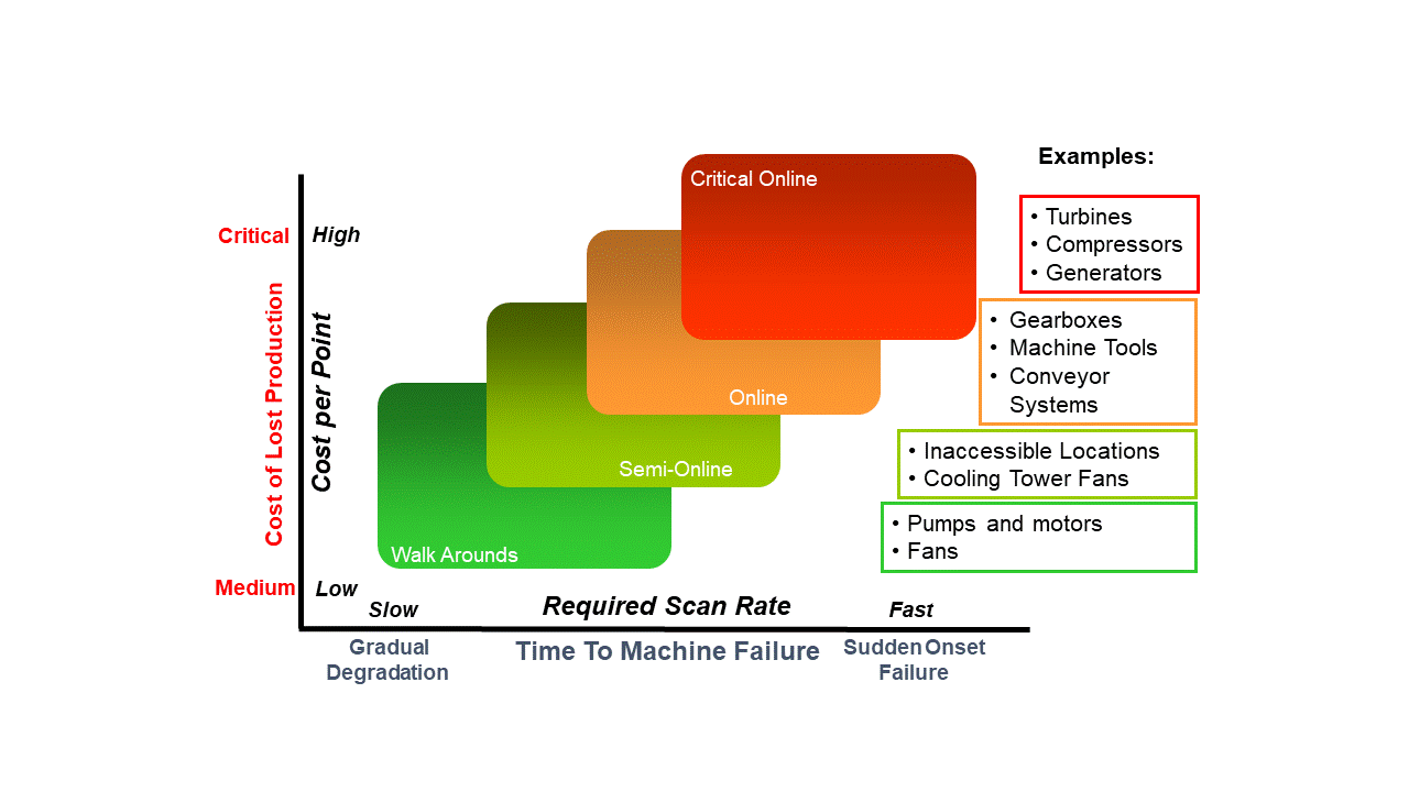
The diagram below outlines the suggestions.

Photo Credit: SKF.
